Teaching
Resources
Concrete-based Constrained Layer Damping
Excerpt from: "Concrete-based Constrained Layer Damping", Precision Engineering Journal of the International Societies for Precision Engineering and Nanotechnology, Vol. 26, No. 4, October 2002, pp. 430-441.
"It only Hertz a little while", Bill Plummer, Polaroid, 2000.
Introduction
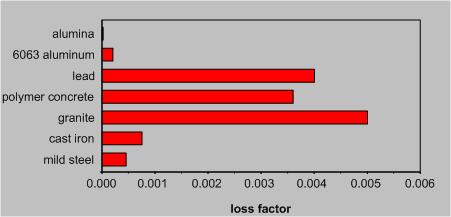
Welded machine tool structures provide easy scalability in terms of size and outstanding flexibility in terms of rapid design and fabrication. The high thermal diffusivity of steel minimizes temperature gradients within the structure, thereby reducing the effects of warping considerably. However, damping of the structure is a very critical issue. Unlike cast iron, polymer concrete, or granite-based components, welded steel plates have virtually no internal damping (Fig. 1). The conventional approach of filling various cavities of the structure with concrete or sand can add damping but also a great deal of mass without any accompanying stiffness.
Source: Lazan, 1969
Constrained-Layer Damping
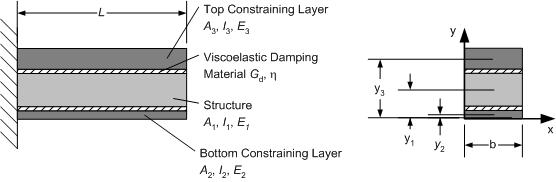
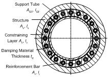
A better approach is the use of constrained layer damping, a concept first conceived by Plass [1] in 1957 and later by Ross, Ungar and Kerwin [2] whose strain-energy approach for a three-layer plate under sinusoidal bending deflections became known as the RUK theory. The principle behind such a system is the following: A viscoelastic material is sandwiched between the structure and one or more constraining layers (Fig. 2). Kinetic energy from relative motion between the structure and the constraining layer as it occurs during bending or twisting gets dissipated by the viscoelastic layer. This mechanism introduces damping into the system, thereby limiting the structure's response to excitation frequencies near its modes [3], [4].
Concrete-Cast Damping Design
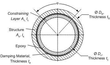
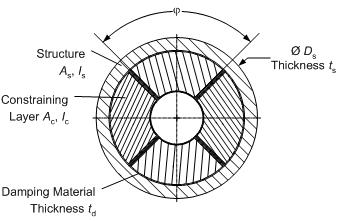
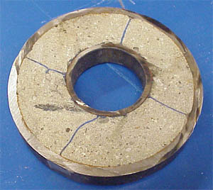
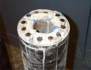
The concrete-cast constrained layer damping design provides a novel solution to an existing internal damping patent, the ShearDamper™ [5], [6]. Instead of using expensive epoxy to fit steel constraining layers made from a slotted steel tube to the inside of a hollow structure (Fig. 3), the new design makes use of a much simpler process. The constraining layers are replicated in-place by using expanding concrete to fill four tubular, viscoelastic inserts, which are placed between the inside of the structure and the outside of a support tube. The inserts are made from viscoelastic ISODAMP™ C-1002, (EAR Specialty Composites, Indianapolis, IN) with a thickness specifically tuned towards the individual structure and a perimeter that ensures that the layers can form completely as illustrated in Fig. 4 (Patent pending).
Eliminating voids is absolutely crucial, otherwise the concrete, as it expands during curing, cannot create the pressure required to keep the constraining layers firmly in place. Therefore, sufficient expansion of the concrete is an essential element of this design and is achieved by adding 1% Intraplast-N™ (SIKA Corp., Reading, MA) to the concrete mixture. This expanding grout agent contains an aluminum powder that oxidizes during the curing of the concrete, thereby producing little hydrogen bubbles which counteract the concrete’s tendency to shrink.
Damping Performance
The performance of such a system is determined by the loss factor of the viscoelastic material and how well the stiffness of the constraining layers is tuned to the stiffness of the structure. For this purpose, Marsh and Hale[7] introduced the stiffness ratio r, the ratio between the sum of the components’ stiffness with respect to the system neutral axis and the sum of the components’ stiffness with respect to their own neutral axes, respectively. The complex goal of maximizing damping is then reduced to maximizing the ratio r.
From this simple equation (1) we take that constraining layers should be as far away as possible from the system neutral axis, but this of course is limited by the fact, that as an internal system, dimensions cannot exceed that of the inside of the structure.
According to Marsh and Hale, the loss factor of such a system can then be determined as:
where hv is the loss factor of the damping material. The damping factor a is given as:
where bi and ti represent the characteristic width and thickness of an individual damping layer and Gv its shear modulus. A table of computed effective lengths Leff, which essentially is dependent on the support conditions of the structure, can be found in Hale’s thesis work [8]. The last important equation in determining damping performance is the calculation of the optimum damping layer thickness:
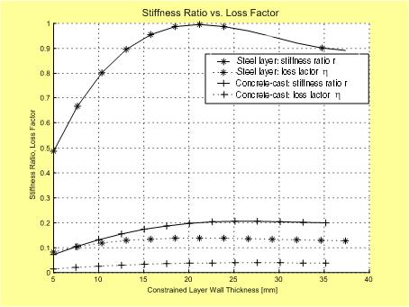
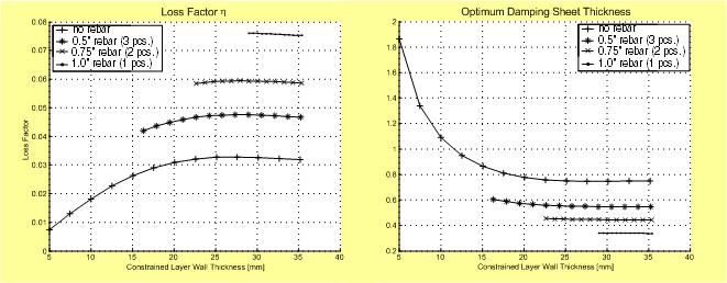
The strong correlation between ratio r and loss factor h is shown in Fig. 5, which plots the two characteristic values against the constraining layer thickness of a round, internal four quadrant system. As can be seen, the steel-based design reaches higher values of r, resulting in better damping compared to the concrete design. The reason for this difference has its roots in the modulus of elasticity, which for steel is several times higher compared to concrete.
However, the primary shortcoming of a steel-based design also becomes apparent: the need to find an inner tube with the largest possible outer diameter to fit inside the structure AND the right wall thickness in order to maximize the stiffness ratio r. The concrete-cast design, on the other hand, removes two of these constraints by using the inner tube as a simple support structure rather than as a constraining layer. The only remaining parameter of importance is the outer dimension of the inner tube because it determines the thickness and with it the stiffness of the concrete constraining layers; the wall thickness and material of the inner tube are no longer of importance, making this design simpler and less expensive.
It should be pointed out that damping performance is also dependent on the thickness of the viscoelastic damping layer, which can only be purchased in certain increments. Steel-based designs generally require very thin damping layers, often much thinner than what is actually available. Concrete-based layers, on the hand, generally require thicker viscoelastic layers and are often close to an actually available thickness.
The effect of the lower Young’s modulus of concrete can be partially offset by adding inexpensive rebars to the constraining layers (Fig. 6). The rebars increase the stiffness of the constraining layers, thereby improving damping performance considerably. This improvement is illustrated in Fig. 7.
Damping Results
The predicted and measured damping ratios for a 89 mm (3.5 in) diameter and 1220 mm (48 in) long structural tube equipped with a four-quadrant concrete-cast damping system and a 48.3 mm (1.9 in) diameter support tube are given in Table 1. It is interesting to note how well theory and experiment agree on the first mode at 280 Hz, while higher modes offer more damping than predicted. This unexpected performance plus might be attributed to the fact that concrete itself has internal damping that is highly frequency-dependent [9][10]. Its influence, however, is not included in the predictions.
The frequency dependency in damping performance is consistent with experimental data from an earlier prototype that was shorter (610 mm long = 24 in) and larger in diameter (140 mm = 5.5 in). As shown in Table 2, loss factors measured at the first bending mode were considerably higher than calculated.
Table 1: Loss Factors for 1220 mm x 89 mm (48 in x 3.5 in) prototype with concrete CastDamper: 1st Mode (283 Hz) 2nd Mode (740 Hz) 3rd Mode (1360 Hz) theoretical 0.0260 0.0263 0.0265 measured 0.0180 0.0430 0.0640
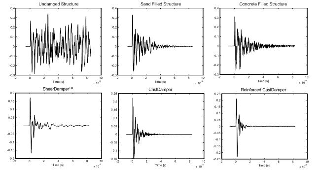
Table 2: Loss factors for 610 mm x 140 mm (24 in x 5.5 in) prototypes (1st mode): ShearDamper CastDamper CastDamper with 0.5 in rebars (3 per layer) theoretical 0.037 0.035 0.044 measured 0.0592 (1530 Hz) 0.1432 (1260 Hz) 0.3308 (1640 Hz) A further indication about the potential of concrete-cast constrained layer dampers can be found in the picture below. Here, the amplitude of the structure as a result of an impulse is shown in the time domain. It is easy to see, how much quicker the vibration becomes attenuated with concrete damper designs; the steel-reinforced damper works especially well, outperforming all other design by a wide margin.
Acknowledgements
I would like to thank Prof. Samir Nayfeh and Kripa Varanasi (both at MIT) for their invaluable help with the modal analysis part of this research.
Publications:
E. Bamberg, A.H. Slocum (2002). Concrete-based constrained layer damping. Precision Engineering, 26(4), pp. 430-441.
E. Bamberg, A.H. Slocum (2001). Concrete-based constrained layer damping. In: Proc. 2001 JSPE Conf., Yokohama, Japan, July 12-19, 2001, pp. 544-548.